Raspberry Pi + LED + Photodiode + Fidget Spinner |
Story location: Home / computing / raspberry_pi / |
| 05/Jun/2017 |
Several years ago I had the idea of using a camera or light sensor to measure how fast a hamster runs in a wheel. I never actually did anything about it but I recently saw a fidget spinner in action and decided to measure its speed using LEDs and a photodiode.
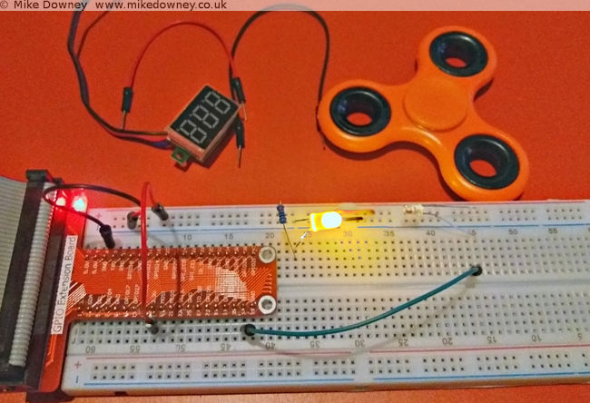
The circuit was incredibly simple. At first I thought I might need to connect the photodiode to an amplifier or schmitt trigger or something like that but when I pointed the LED directly into the photodiode and attached the voltmeter to the latter, the voltage went close to zero when I blocked the light and went over 3v when I let the light through. It looked like I could just connect the photodiode directly to a GPIO pin of the Raspberry Pi to measure when the light path was blocked.
The next step was to write some code to detect when the GPIO pin changed state and to measure the frequency. When I logged into the Pi, I found a script which actually did exactly that. I'm not entirely sure where this came from. I may have adapted it from a C exmaple from the pigpio project but I can't actually remember. It uses NumPy to calculate the average.
Wiring it up
Connecct the LED to the 3.3V output of the Pi, through a 220 ohm resistor. Connect the photodiode 'in reverse': the long leg to GPIO 26 of the Raspberry Pi and the short leg to the 3.3v supply. When the light level is low, the photodiode will act like a normal diode and block the current. When the light level is high, the current will flow and the GPIO pin will detect a 'high' signal.
Results

I fired up the edge.py script, started the figet spinner and lowered it into into the light beam. I had to be careful to avoid it touching the breadboard, the LED or the photodiode so I almost certainly didn't manage to spin it as fast as I could. I ran the script a few times and got numbers between 30-50 Hz. Since the spinner had 3 lobes, this means that it was only spinning between 10 and 15 times per second.
Matt Parker has a video where he uses a spectrum analyser to measure the frequency of the spinner. He uses a compressed air can to reach much higher speeds.
Using the Raspberry Pi serial port from Java |
Story location: Home / computing / raspberry_pi / |
| 25/Feb/2017 |
A couple of days ago I wrote about connecting the Raspberry Pi to the NodeMCU microprocessor board. I originally used Python since I find that the easiest for testing ideas or simple prototyping. Since I use Java for most of my application programming, I thought I should work out how to do the same thing in Java too.
Luckily there is a Java serial comms library called RxTx which is available precompiled for Debian Linux and can be installed on the Raspberry Pi simply by typing
sudo apt-get install librxtx-java
The jar file is placed in /usr/share/java/RXTXcomm.jar (and doesn't seem to be added automatically to the classpath) so to compile any code, you'll need to use something like
javac -cp /usr/share/java/RXTXcomm.jar:. SerialTest.java
and to run the code you need to reference both the jar and the JNI library, using
java -cp /usr/share/java/RXTXcomm.jar:. -Djava.library.path=/usr/lib/jni SerialTest
The Code
import gnu.io.CommPort;
import gnu.io.CommPortIdentifier;
import gnu.io.SerialPort;

import java.io.*
import java.util.Scanner;

public class SerialTest{

    public static void main(String[] args) throws Exception{
        CommPortIdentifier portIdentifier = CommPortIdentifier.getPortIdentifier("/dev/ttyS0");
        CommPort commPort = portIdentifier.open("Java Serial Test",1000);
        System.out.println("Opened Port");

        SerialPort serialPort = (SerialPort) commPort;
                serialPort.setSerialPortParams(115200,SerialPort.DATABITS_8,SerialPort.STOPBITS_1,SerialPort.PARITY_NONE);

        String[] leds = new String[]{"r","g","b","off"};

                try(BufferedInputStream in = new BufferedInputStream(serialPort.getInputStream());
                BufferedOutputStream out = new BufferedOutputStream(serialPort.getOutputStream());
        Scanner s = new Scanner(in)){

            for(String c : leds){
                out.write(c.getBytes());
                out.flush();
                System.out.println(s.next());
                Thread.sleep(1000);
            }
        }
    }
}
I saved the code as SerialTest.java and compiled it and ran it using the commands above. It expects the serial.lua file to already be running on the NodeMCU board, either by running the python script from last time or by executing
python nodemcu-uploader.py --port /dev/serial0 file do serial.lua
As you can see, the code is much more verbose than the Python version but it gets the job done.
The long awaited Raspberry Pi post: Interfacing with a NodeMCU |
Story location: Home / computing / raspberry_pi / |
| 22/Feb/2017 |
I first used a Raspberry Pi when I was working in Leicester and I bought one for home not long after that. I set it up as a file/media server and it has been sitting in the front room quietly doing its job since then.
Last year I bought a Pi 3 and an electronics starter kit (which consisted of a breadboard, LEDs, switches and various other components) so I could learn how to connect things to the Pi.
A few weeks ago I was given a NodeMCU development board (my friend Tim has already written about some of his experiments with his).
I followed the instructions on flashing the firmware and getting a script running. For some reason the ESPlorer software doesn't seem to behave well on my computer. It usually takes several rounds of restarting/resetting/reconnecting before it will agree to communicate with it. The command line tools have no problems, neither does CoolTerm. After a day when it felt like I was spending half of my time struggling to get ESPlorer to connect properly, I decided to ditch it and use the nodemcu-uploader command line instead.
The first thing I wrote was the Hello World of the microcontroller world: the flashing LEDs. The next stage was to use the serial ports to connect the Raspberry Pi and the NodeMCU together.
Setting up the Raspberry Pi Serial Port
By default, the serial port on the Pi is configured to be used for a serial console , mainly for diagnostics. To use it for other things, you need to disable the console. There are lots of different instructions to do this but for the Pi 3 it boils down to editing the /boot/config.txt file and adding the line
enable_uart=1
followed by editing /boot/cmdline.txt and removing the
console=serial0,115200
entry. After rebooting the Pi, the GPIO pins 14 & 15 should be available for the serial port.
Writing the script for the NodeMCU
I took my flashing LED script and modified it to listen to the serial port. Sending 'r','g' or 'b' will light up the respective LEDs, any other character will turn them off. If the following script is saved as serial.lua, it can be uploaded to the NodeMCU using
python nodemcu-uploader.py -port /dev/serial0 upload serial.lua
as long as the NodeMCU Uploader has been installed first.
-- Listen on the serial port for a colour.
-- Toggle the colour of the LED.

green=2
blue=1
red=3
gpio.mode(red,gpio.OUTPUT)
gpio.mode(green,gpio.OUTPUT)
gpio.mode(blue,gpio.OUTPUT)

-- Start with the LEDs off
gpio.write(red,gpio.LOW)
gpio.write(green,gpio.LOW)
gpio.write(blue,gpio.LOW)

uart.setup(0,115200,8, uart.PARITY_NONE, uart.STOPBITS_1, 1)

uart.on("data",1,
    function(char)
        if char=="r" then
            print("red")
            gpio.write(red,gpio.HIGH)
            gpio.write(green,gpio.LOW)
            gpio.write(blue,gpio.LOW)
        elseif char=="g" then
            print("green")
            gpio.write(red,gpio.LOW)
            gpio.write(green,gpio.HIGH)
            gpio.write(blue,gpio.LOW)
            lighton=2
        elseif char=="b" then
            print("blue")
            gpio.write(red,gpio.LOW)
            gpio.write(green,gpio.LOW)
            gpio.write(blue,gpio.HIGH)
        else
            print("Off")
            gpio.write(red,gpio.LOW)
            gpio.write(green,gpio.LOW)
            gpio.write(blue,gpio.LOW)
        end
    end,0)
The script can be run using
python nodemcu-uploader.py -port /dev/serial0 file do serial.lua
Getting the Pi to talk to the NodeMCU
I connected the RX GPIO pin on the Pi to the TX pin on the NodeMCU, and vice versa. The easiest way of powering the NodeMCU was to use the power out pins from the Pi. I found that connecting the 5V out to Vin on the NodeMCU worked reliably. If I had the Pi plugged into a good quality USB power adaptor then I could sometimes get it to work by connecting one of the 3.3V pins of the Pi to one of the 3.3V pins of the NodeMCU board, but this isn't guaranteed to work.
The script uses the serial port library, which can be installed using
sudo apt-get install python-serial
The Python script is fairly simple and just cycles through the LEDs a few times. The third line runs the lua script, in case it wasn't already running. There isn't a pause between cycling between the LEDs but the serial timeout is set to 1 second and the port.read(100) command attempts to read 100 bytes. Since there should only be the colour names being returned, this automatically adds a 1 second delay. This might not be very good programming practice but it was the easiest way of incorporating reading a variable length response and adding a pause all at once.
import serial

port = serial.Serial("/dev/serial0", baudrate=115200, parity=serial.PARITY_NONE, timeout=1.0)

port.write("dofile('serial.lua')\r\n")

for i in range(1,10):
    for c in ['r','g','b']:
    port.write(c)
        r = port.read(100)
        print(r)
Flashing LEDs
This first demonstration is pretty trivial, although it took a few days of trial and error to get everything working. In due course I'll experiment with connecting different sensors to the Pi and NodeMCU.
I think my next step is to use Java on the Pi to do the same thing. I have had a quick look at Java serial port stuff and it isn't as straightforward as Python but since I do most of my programming in Java these days, it will be useful to know how to do that.