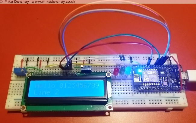
When I bought the electronics starter kit for the Raspberry Pi, it came with a small 16 character by 2 line LCD. I found instructions on the Adafruit website for wiring it up and controlling it. I thought it might also be a useful thing to use with the NodeMCU board so I had a look for any instructions for that.
Unfortunately everything I found was for the I2C version of the display and I've got the plain parallel bus version, so I decided to have a go at wiring it up and programming it myself.
Wiring up the board
The wiring is quite straightforward, although a lot of wires are required. Six GPIO pins are needed at the NodeMCU end, along with power and ground.
Starting with the power pins, connect one of the ground pins from the NodeMCU to the ground rail of the breadboard. The 'Vin' pin supplies 5 volts (if used with a usb connection) so connect a wire from that to the '+' rail of the breadboard.
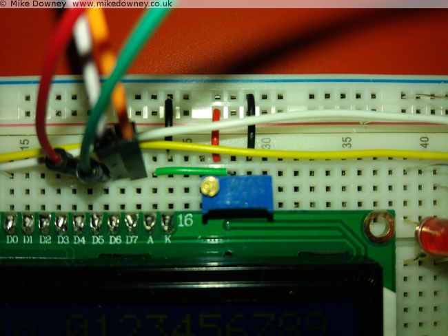
Four data lines are required: D4-D7 on the LCD. To make things easier I connected these to pins 4-7 on the NodeMCU board. The final two connections from the NodeMCU are 'Clock' (called 'E' on the display board) which went to pin 2, and 'RS' which went to pin 1. Data line D0-D3 from the display board are left unconnected.
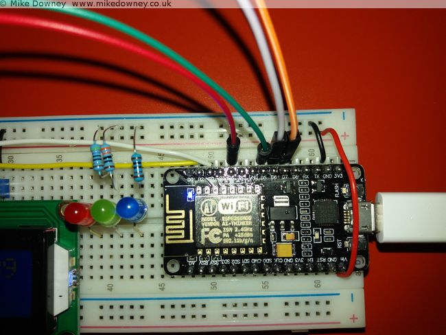
The rest of the pins on the board go to either 0V, 5V or a potentiometer set as a voltage divider (ignore the 3 LEDs in the pictures, they aren't needed here).
Connect the following pins to ground (0V):
- 'RW' (set permanently to Write mode since we aren't reading from the board)
- 'VSS' (the board's ground connection)
- 'K' (the ground connection for the backlight)
- One side of the two potentiometers.
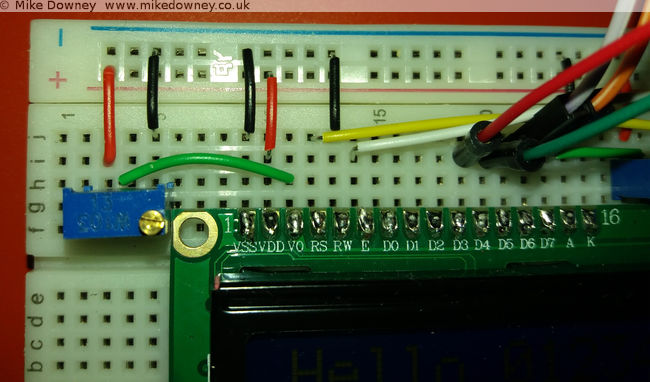
Connect the 'VDD' pin to 5V and also the other side of the two 10K potentiometers. Finally, the 'V0' and 'A' pins can be connected to the centre of the two potentiometers to provied adjustable contrast and backlight.
Programming the board
I based my Lua code on the Python code downloaded from the Adafruit website. Since I was converting the code from one language to another, I read through it carefully to make sure I only converted the bare minimum to get it working.
My first version of the code was little more than a few subroutines to send bytes to the board. While I was reading the NodeMCU Lua FAQ, I noticed that they recommend that code is written to be event driven instead of the more traditional program flow used in scripting. They also state that routines called from an event can only take a maximum of 10 milliseconds to run before they affect background services. After reading that I changed my code to buffer the text and use a timer to check the buffer and send the bytes to the display.
The current version is probably too cautious and sends a byte at a time. It might be more efficient to send a line at a time but that should be easy to change.
The code can be found over on Github. I have decided to put it there since it is easier for me to keep it up to date and easier for anyone else to download.